

Good afternoon. The program FLProg since version 2.1. appeared blocks menu. In this lesson we will create a menu using the data blocks.
That would be more interesting to consider the real-world task. Collect a temperature control unit, which will include a temperature sensor, a heater and a fan. Additionally, the inclusion of a fan or heater will be accompanied by an audible signal. Menu will be to set thresholds on and off devices and the need of a sound signal. For easier debugging the temperature sensor to start going to simulate with a variable resistor.
The first variant of the device will consist of:
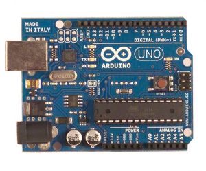
Arduino Uno:
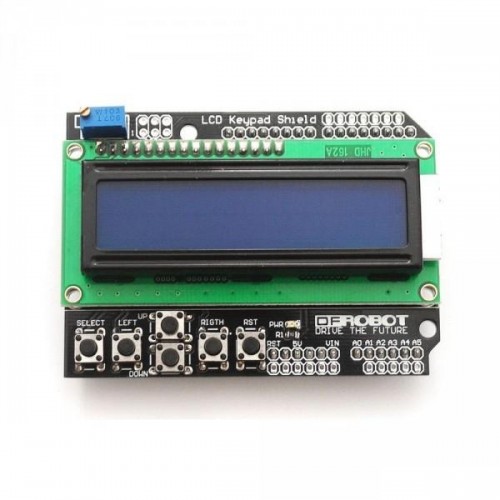
LCD Keypad Shield
The two relay blocks:
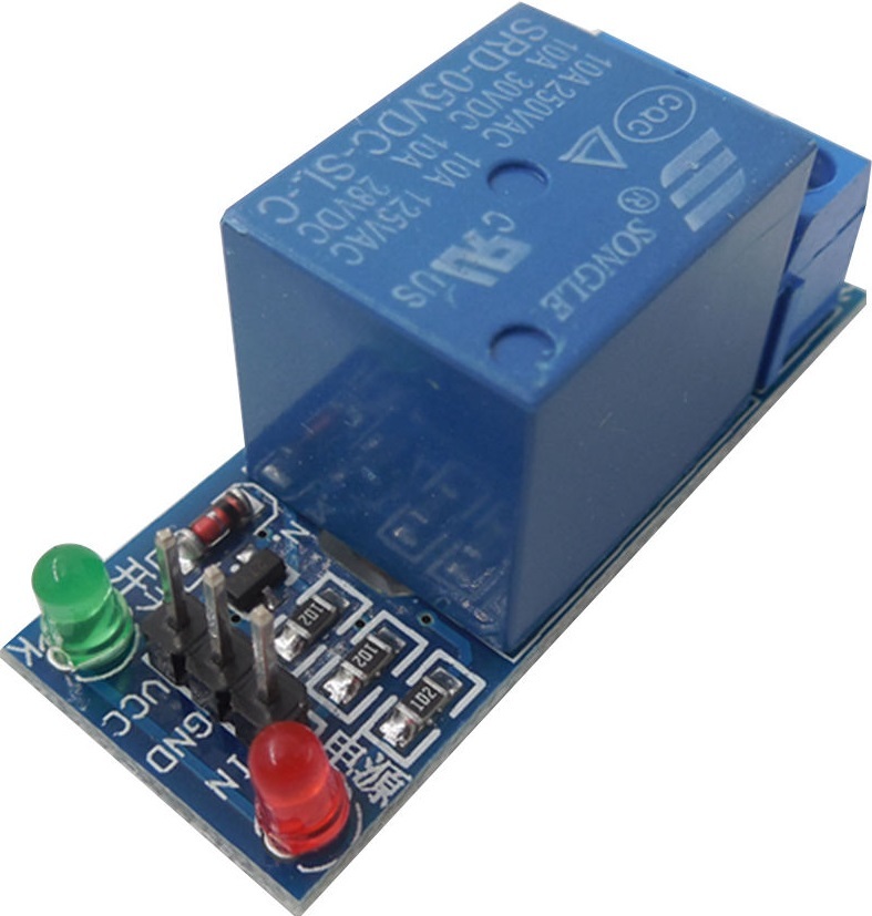
Active buzzer:

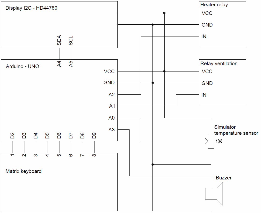
Here is a schematic diagram of the device
To start the whole project.
Consider each charge separately.
Everything here is just get the value from an analog input and scale in the required range. The temperature value will change from -20 to 80. Settings block Scale.
This Board analyzes the signal of the buttons on LCD Keypad Shield and are formed corresponding signals. The analysis is performed using the user unit 5Bin1. The creation of this unit covered in this lesson, there you can download this block.
Since the buttons on the Silde is not enough, let’s add functionality to the “Select” button.
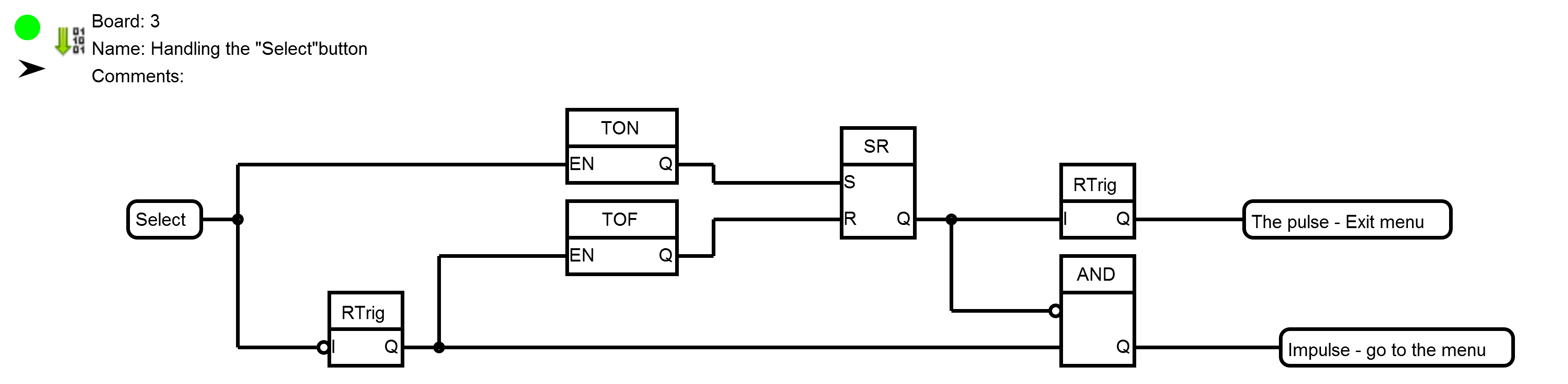
This scheme works as follows. Short press on button momentum “to Go” menu, with prolonged (duration more than the set point of the timer TON), momentum “Exit”.

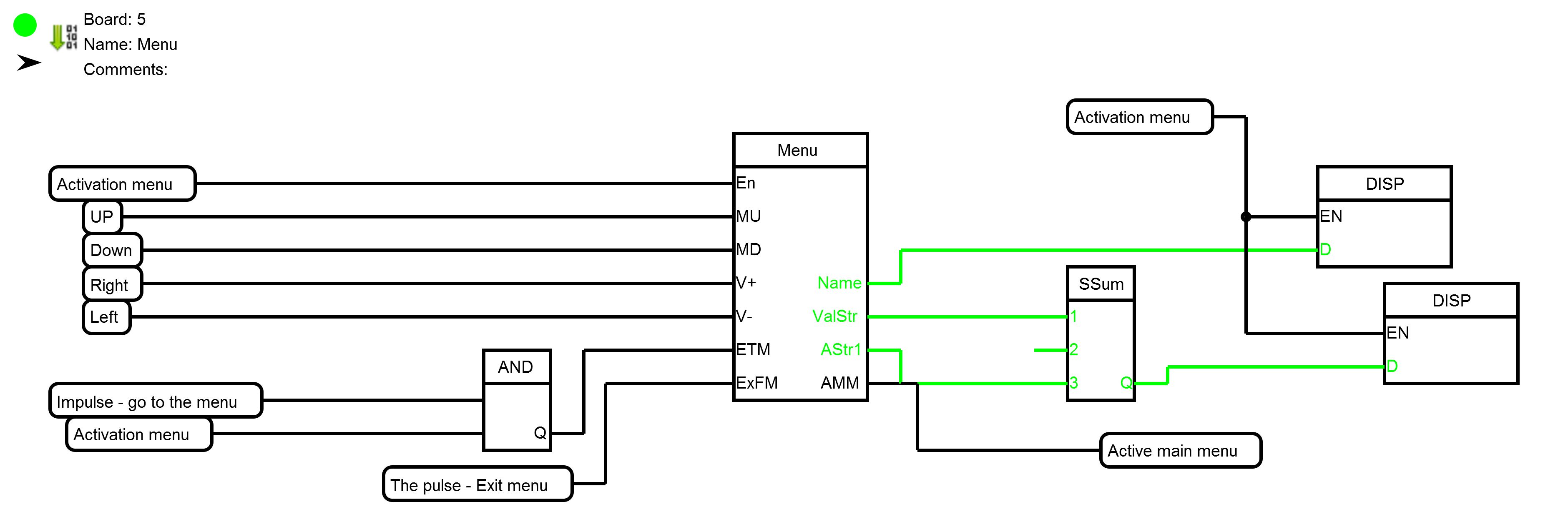
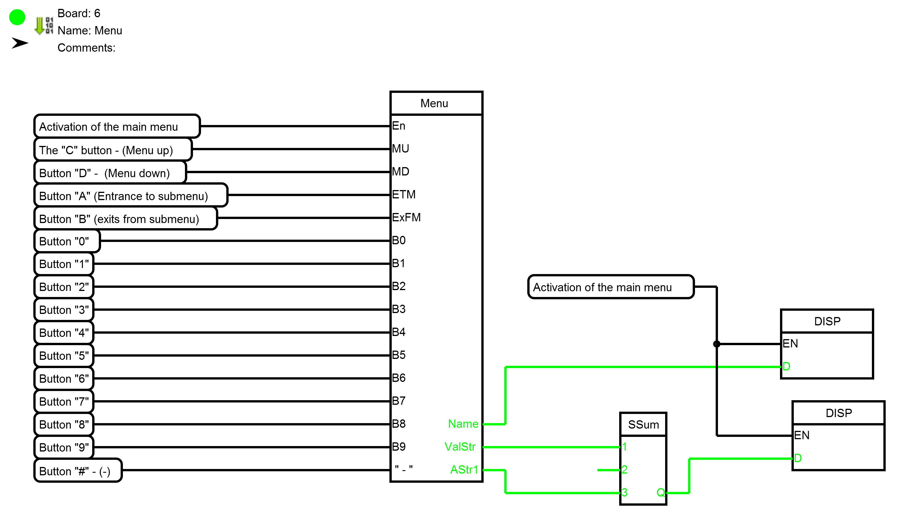
On this Board a signal is generated activating the menu. Timer TON necessary to protect against the accidental formation of this signal at the start of the controller. Well, just charge with the main menu block.
In the description of the unit menu (tab “Information” editor’s block) I tried to fully describe the operation of the unit. Consider the tincture of the block in this particular case.
Tab “Menu Tree”
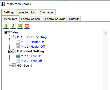
The tree menu consists of two menu groups of settings for temperature on and off of the heater and ventilation, as well as single point to control the activity of sound. In General this unit allows you to build menus of any complexity and nesting. The main thing that would be enough controller memory.
Configure group menu item.
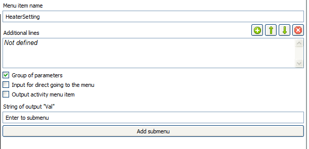
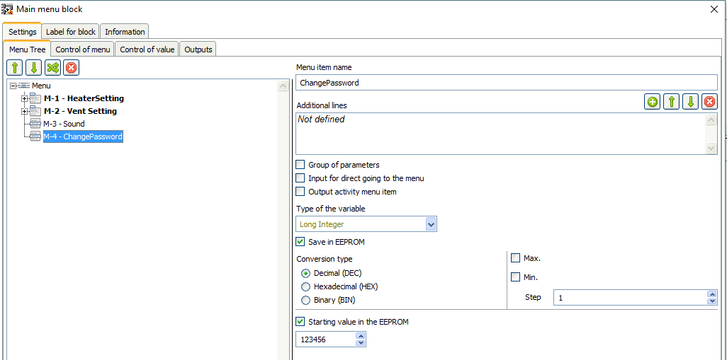
Setting items temperature settings.
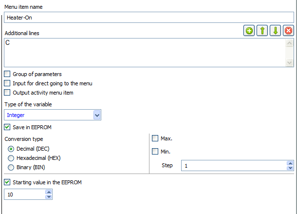
A little bit more precise about the starting values in the EEPROM. This value is recorded in the EEPROM at the beginning of the first cycle after the program is loaded into the controller. This will only happen once after each new loading of the program into the controller. Other menu items associated with a temperature similar to this.
Settings menu sound control:

Texts for True and False will be displayed on the output ValStr, with the corresponding values of the menu items.
Tab – “Control of menu”:
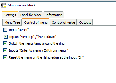
It seems to be intuitive.
Tab – “Controlof value”

The mode changes when you short press the button change the value it changes the value of a given step. If you hold this button more than 2 seconds the value will change by the amount specified step every half second. If you continue to hold the button for 2 seconds, the period value changes will be reduced to 200 ms.
Tab “Outputs”

Exit “Active menu” is needed for the signal “Activate menu”. The next two boards are almost identical, and in special explanations does not need.
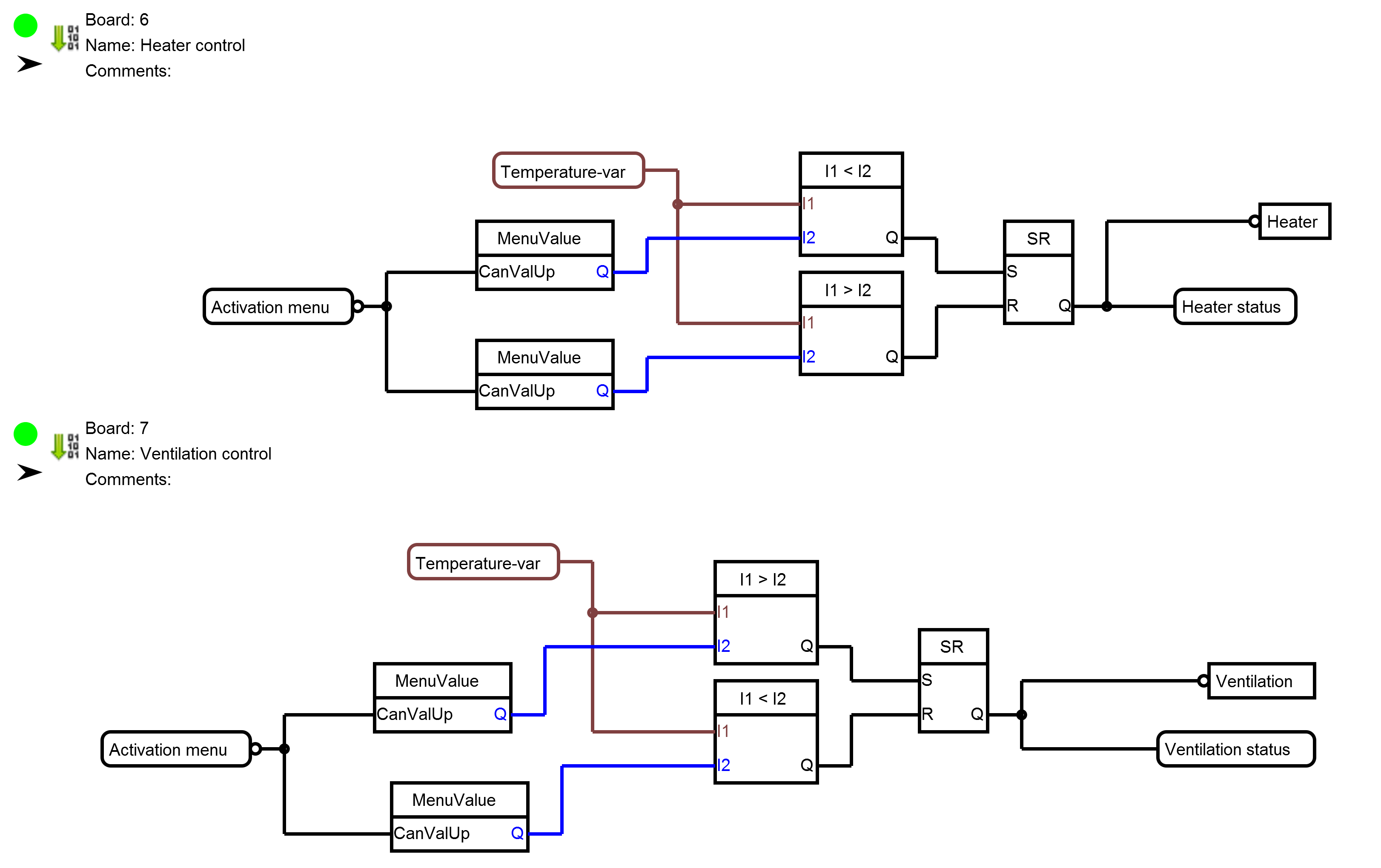
Pay attention only to the inputs CanValUp units MenuValue. At a high level on this input value at the output Q corresponds to the value of the selected menu item. On the falling edge on this input value is “frozen” before the advent of this high level. This is necessary to ensure that the value does not change until the end you edit it (close the menu).
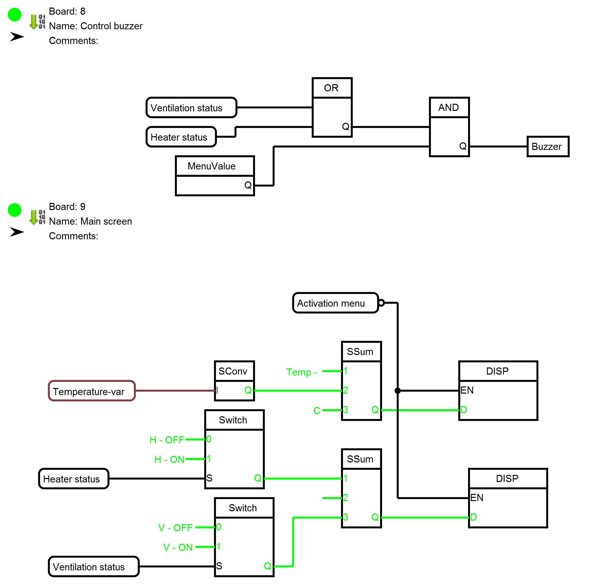
The remaining fee simple and need no explanation.
Now a little “bleed” project. Replace LCD Keypad Shield for 4×4 keypad matrix and 4×20 display connected via I2C.
This will allow you to set value is not step by step, and by simply entering the numbers. In addition this will make to enter the menu password. Modified scheme of the project.

The entire project.
Consider the modified board
Uses a standard survey unit matrix keypad library elements.
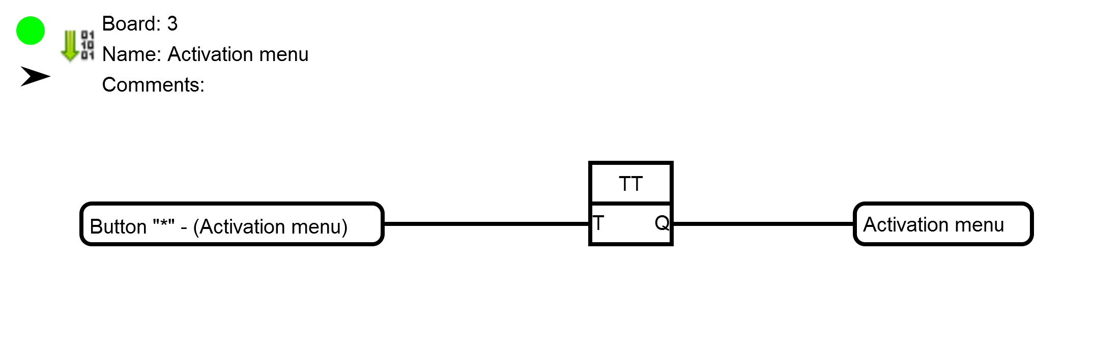
Pressing “*” menu. Only this time, not the main menu, and menu for entering the password.
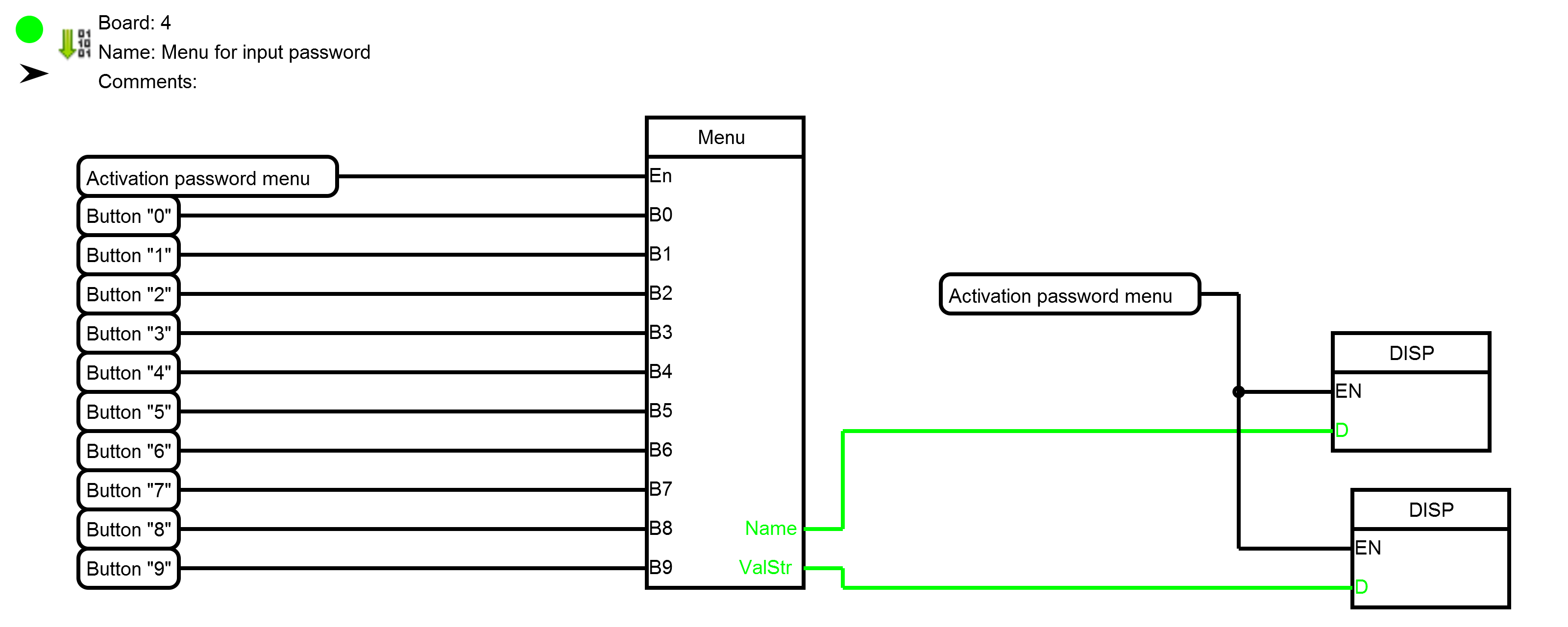
Settings password menu

This menu consists of one item, an employee for a password. Used type Long Integer, to increase the number of characters of the password.
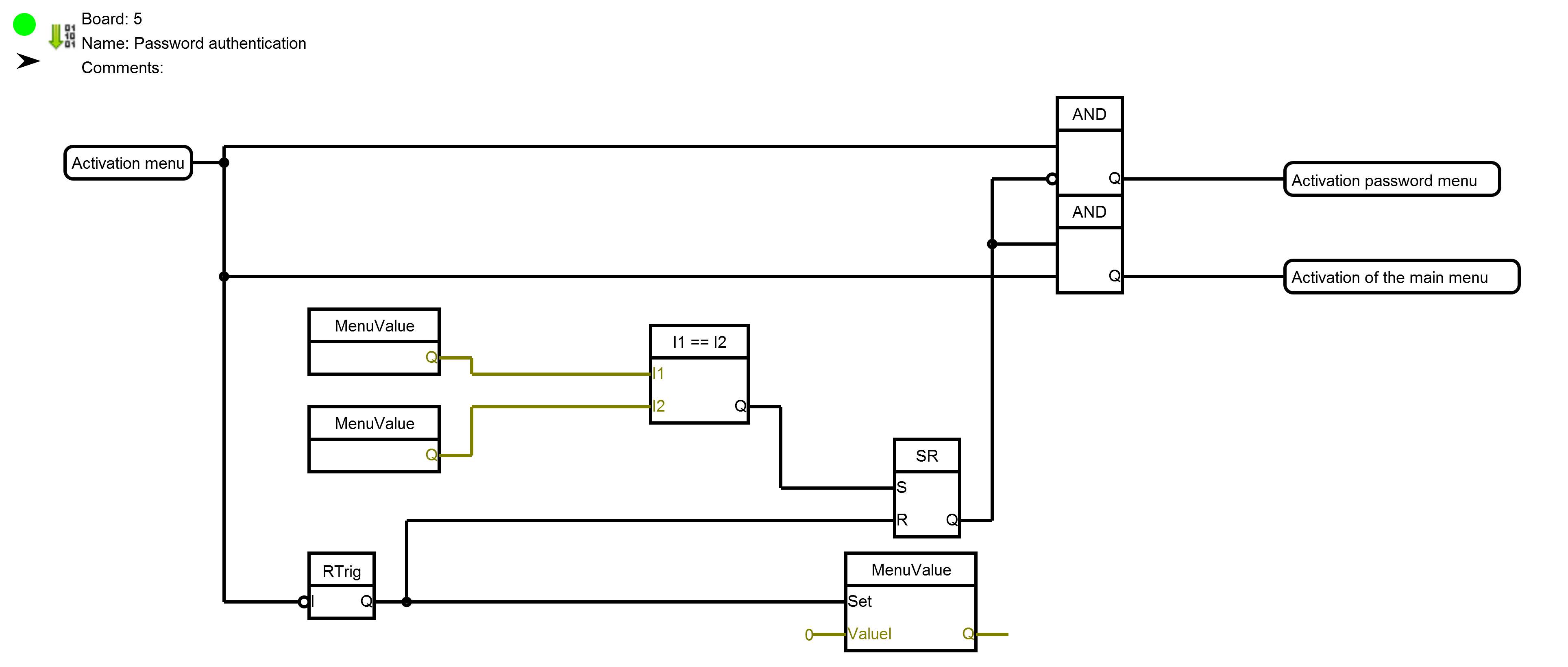
This Board is of the correct password. The coincidence of the password entered and saved in the main menu activates the main menu. When you exit the menu to enter the password is written to 0 (to prepare for next input)
In the main tree menu has been added to configure a stored password.
The same changes were made to the bookmark “Control of value”
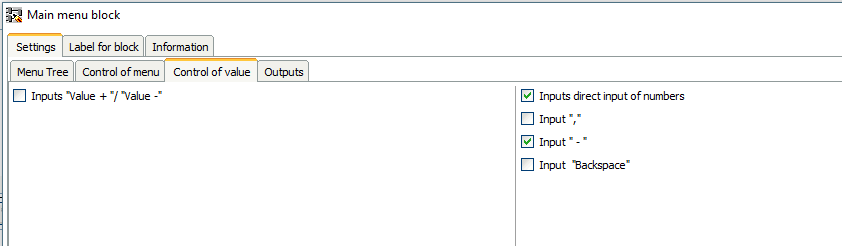
The control value is translated to a direct input of digits. The other Board has not changed.
The use of a resistor as reference temperature useful for debugging, but in real application still required a temperature sensor. Use a temperature sensor DS18B20. To do this, you must change the first cost of both projects.
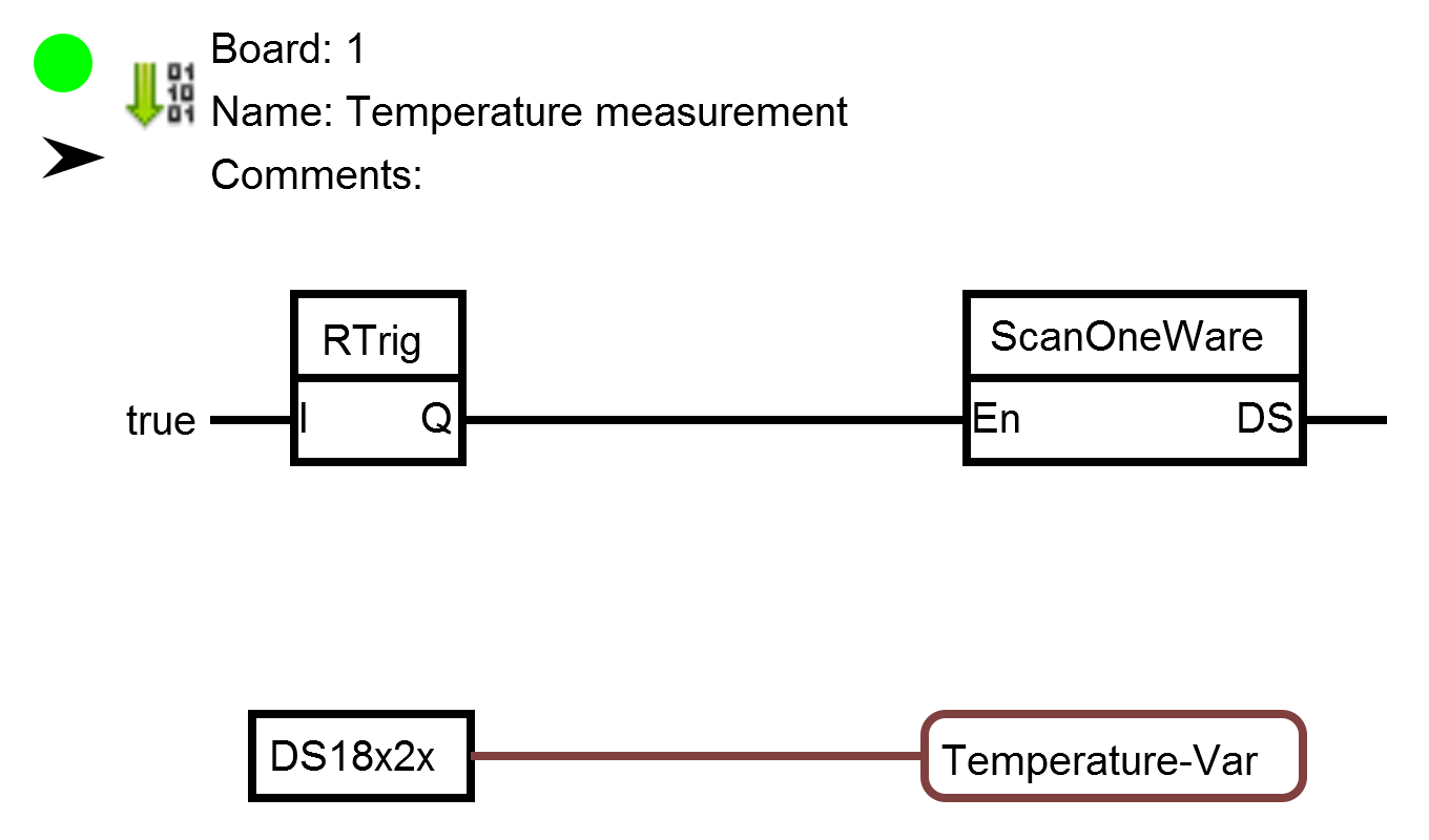
Block “ScanOneWare” is used to automatically determine the address of the sensor. This enables you to replace if necessary temperature sensor without flashing the controller.
Modified concepts
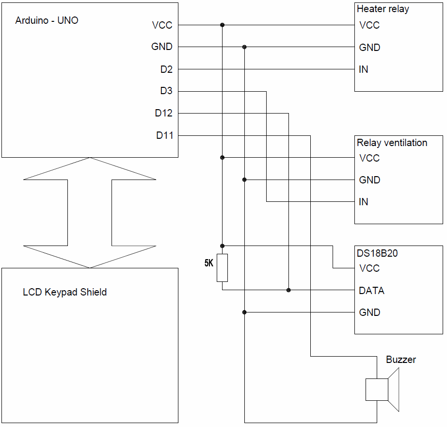 Diagram of matrix keyboard
Source projects
“The circuit with a LCD Keypad Shield and resistor
“The circuit with a Keypad LCD Shield and sensor
“Scheme with a matrix keyboard and a resistor
“Scheme with a matrix keypad and sensor


Здравствуйте Схема с матричной клавиатурой и датчиком не открывается
Файлы отсутствуют
Добрый день! собрал схему кнопки select, не работает , в меню заходит ,а когда жму выход 2 секунды он сразу делает вход ,кнопка управления минус сигнал инвертирую, может я где-то ошибся , есть готовая схема проект ?
Добрый день. Уже нет необходимости в делать меню из блоков. В программе есть отдельный блок меню, он намного удобнее.
Большое спасибо Сергею Глушенко за работу над проектом! Подтверждаю слова sergey.ananev если кнопку держать больше 2с происходит импульс на выход из меню! Но при отпускании кнопки происходит импульс на вход в меню в меню опять! И добавление задержки как предлагает sergey.ananev, удаляет эту проблему! Я пробовал эту плату отдельно, и увидел это своими глазами на светодиодах!
Сергей спасибо за ваши труд. Все получается и работает!
Отсутствует файл “Схема с LCD Keypad Shield и датчиком” – ссылка на яндекс диск битая.
Здравствуйте, Сергей!
1.Файл по ссылке “Схема с LCD Keypad Shield и датчиком” отсутствует.
2. В случае загрузки первого варианта “Схема с LCD Keypad Shield и резистором” по Вашей ссылке в микроконтроллер не будет работать выход из меню при длительном нажатии на кнопку “select”. Сначала микроконтроллер будет выходить из меню, а потом заново заходить в него. На плате №3 “обработка кнопки “select” не хватает таймера TOF между SR и AND.
Познавательно увидеть создание скетча от разработчика.
ПС.”Анализ производится с помощью пользовательского блока 5Bin1. Создание данного блока рассматривается в этом уроке, там же можно скачать этот блок.” – тут ссылка ведет в никуда. и данный пользовательский блок не находиться по поиску.
ППС: НЕработет регистрация нового пользователя
ПППС: может мен кто подробнее объяснить работу Плата №5 проверка пароля. Откуда там уже 3 значинений с меню
Исправил