
Attention!
STM32 support has appeared in the FLProg program since version 8.0.1.
Arduino and ESP controllers, in accordance with this instruction, can be added in earlier versions.
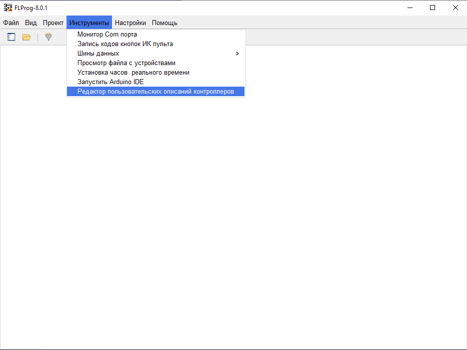
Open the FLProg program. In the main menu, select the “Tools” item, and in it “Editor of custom controller descriptions”.
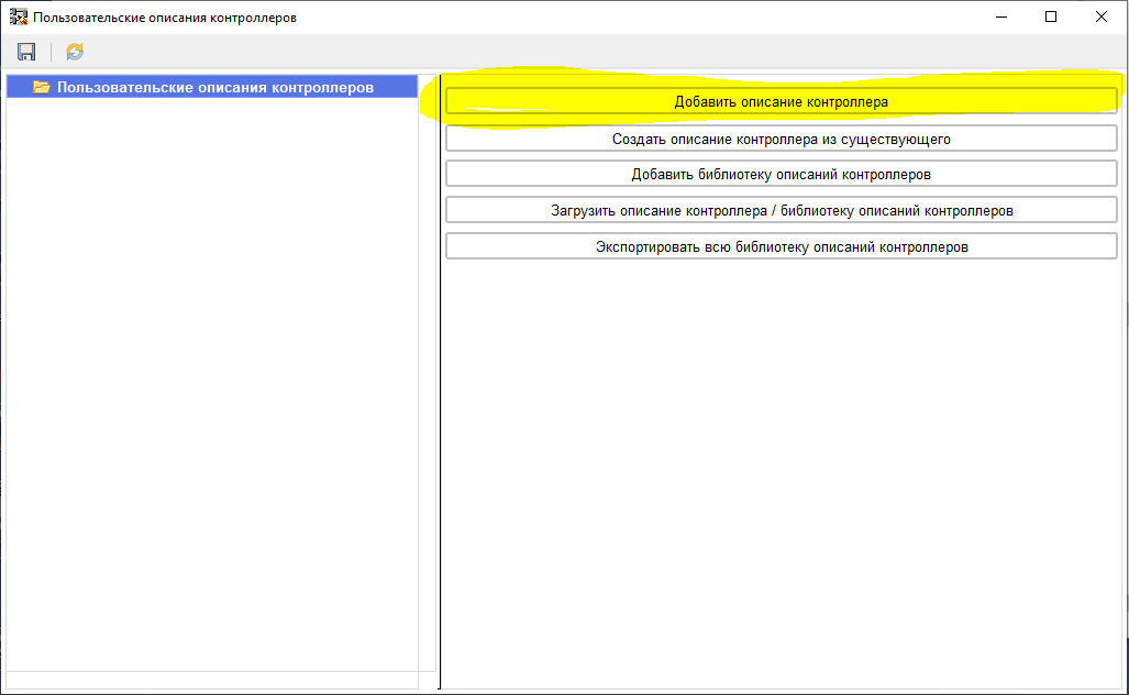
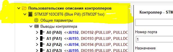
The editor window opens. In it we add a new description of the controller.
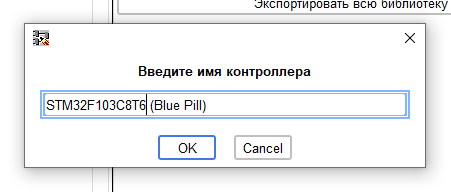
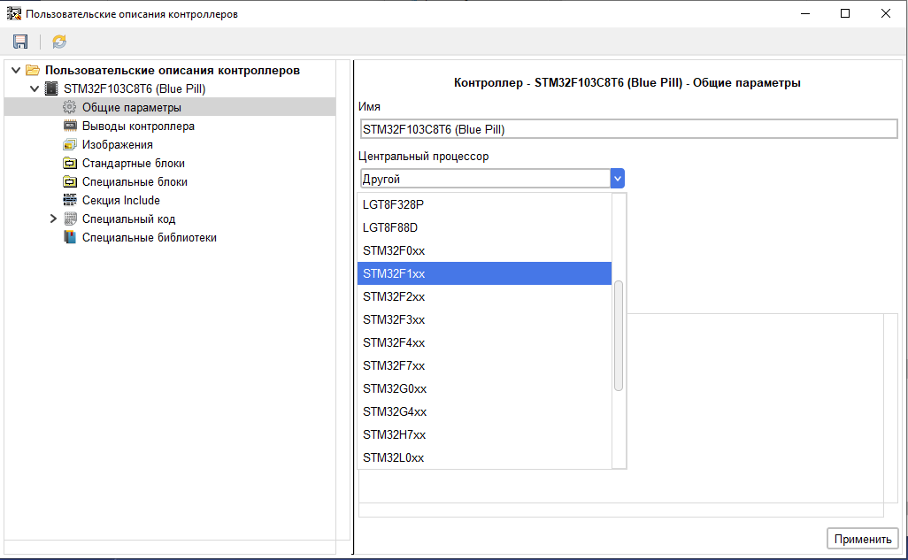
Enter the name of the controller.
After adding a description, go to the “General Settings” branch and select the type of CPU used.
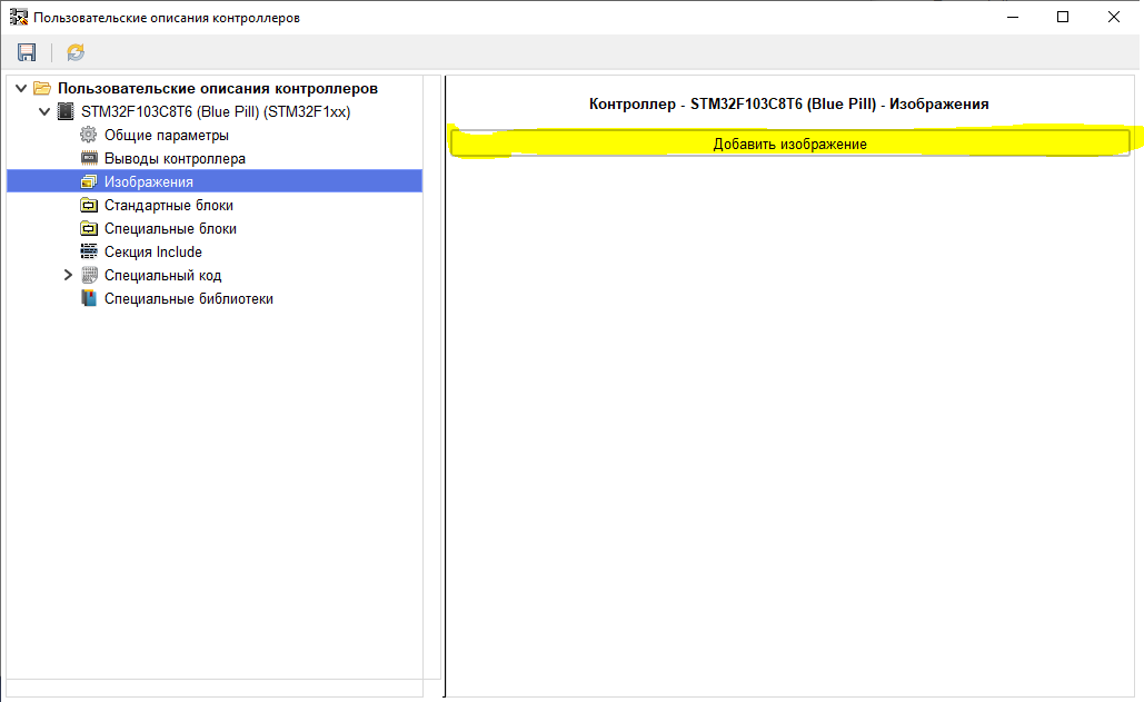
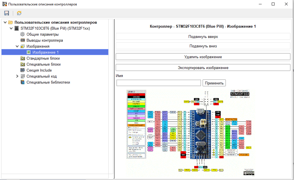
Then go to the “Images” branch and upload the necessary images to the description.
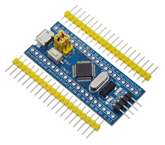
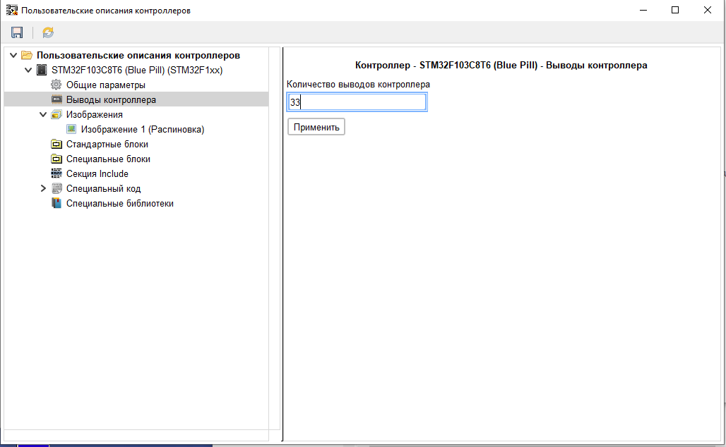
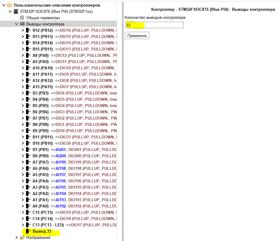
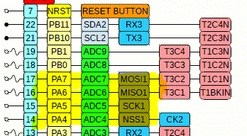
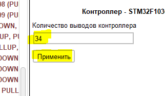
In accordance with the pinout of the controller, we set the number of pins of the board.
For each pin, we set the main name (usually the name that is printed on the board is used) and, if desired, an additional one (alias). After the task, we add the functions of this output.
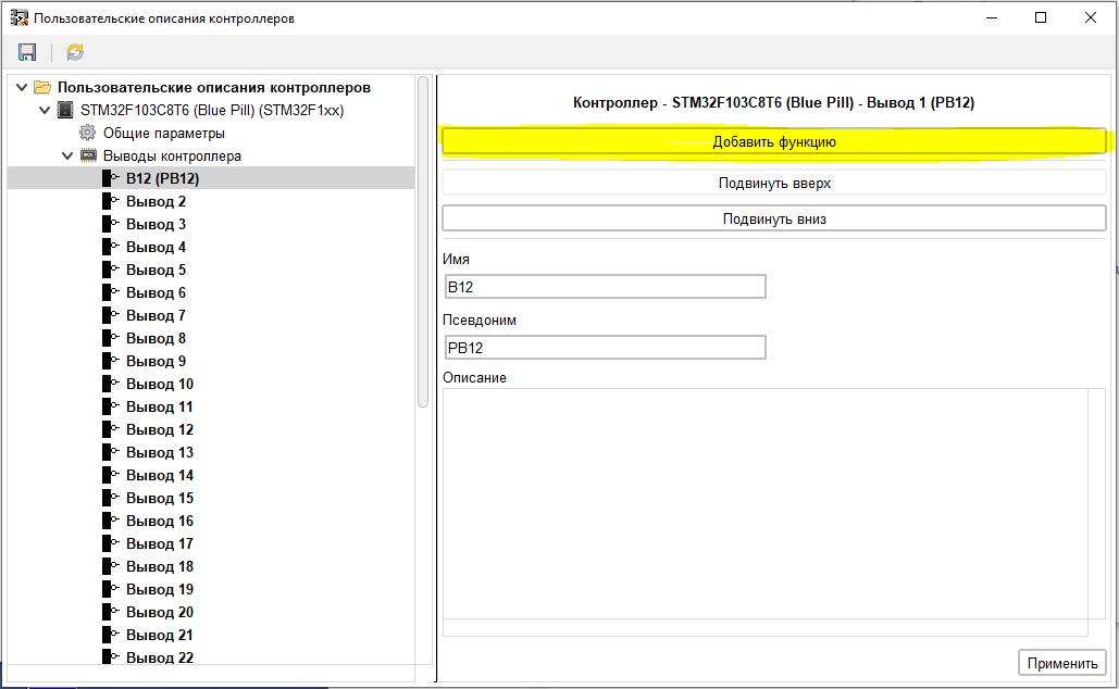
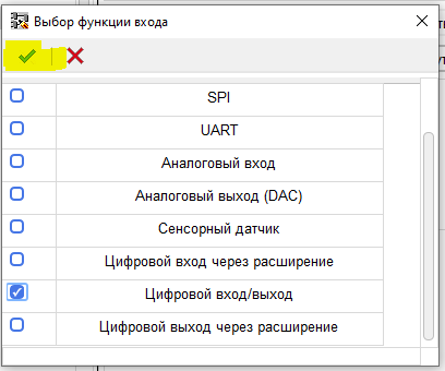
We add the function of digital input – output.
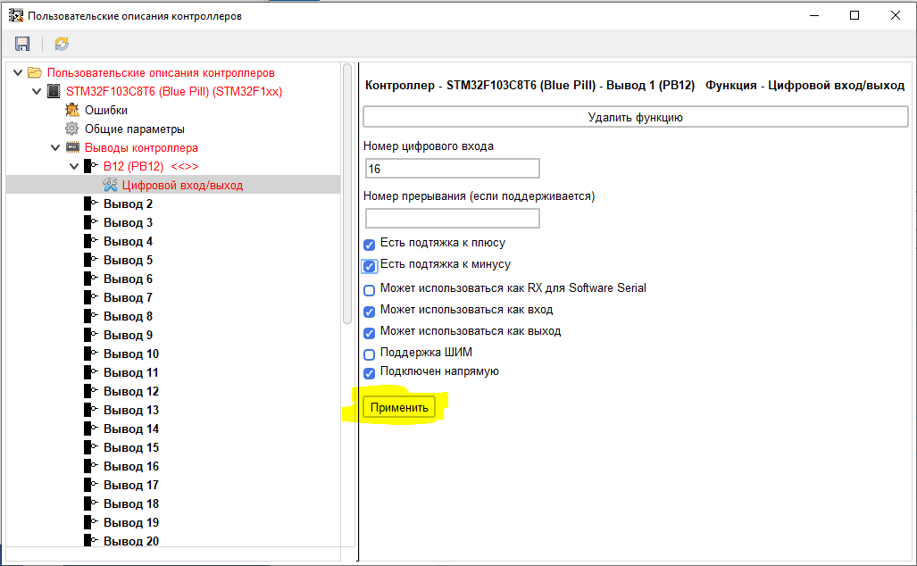
And set the parameters of this function. According to the documentation for the board.
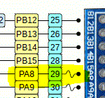
Please note that in the Arduino and ESP controllers, when programming in the ArduinoIDE, digital pin designations are used. Accordingly, in the editor of user descriptions, digital identifiers are also used. For STM, the examples and description use textual descriptions like “PC13”. In fact, these are numeric constants declared in the kernel, calculated depending on the CPU used. To determine the digital values of these constants, the following sketch was loaded into the board.
Sketch Code
void setup() {
// put your setup code here, to run once:
Serial1.begin(9600);
delay(2000);
int temp = PB12;
Serial1.print(“PB12 – “);
Serial1.println(temp);
temp = PB13;
Serial1.print(“PB13 – “);
Serial1.println(temp);
temp = PB14;
Serial1.print(“PB14 – “);
Serial1.println(temp);
temp = PB15;
Serial1.print(“PB15 – “);
Serial1.println(temp);
temp = PA8;
Serial1.print(“PA8 – “);
Serial1.println(temp);
temp = PA9;
Serial1.print(“PA9 – “);
Serial1.println(temp);
temp = PA10;
Serial1.print(“PA10 – “);
Serial1.println(temp);
temp = PA11;
Serial1.print(“PA11 – “);
Serial1.println(temp);
temp = PA12;
Serial1.print(“PA12 – “);
Serial1.println(temp);
temp = PA15;
Serial1.print(“PA15 – “);
Serial1.println(temp);
temp = PB3;
Serial1.print(“PB3 – “);
Serial1.println(temp);
temp = PB4;
Serial1.print(“PB4 – “);
Serial1.println(temp);
temp = PB5;
Serial1.print(“PB5 – “);
Serial1.println(temp);
temp = PB6;
Serial1.print(“PB6 – “);
Serial1.println(temp);
temp = PB7;
Serial1.print(“PB7 – “);
Serial1.println(temp);
temp = PB8;
Serial1.print(“PB8 – “);
Serial1.println(temp);
temp = PB9;
Serial1.print(“PB9 – “);
Serial1.println(temp);
temp = PB10;
Serial1.print(“PB10 – “);
Serial1.println(temp);
temp = PB11;
Serial1.print(“PB11 – “);
Serial1.println(temp);
temp = PB1;
Serial1.print(“PB1 – “);
Serial1.println(temp);
temp = PB0;
Serial1.print(“PB0 – “);
Serial1.println(temp);
temp = PA7;
Serial1.print(“PA7 – “);
Serial1.println(temp);
temp = PA6;
Serial1.print(“PA6 – “);
Serial1.println(temp);
temp = PA5;
Serial1.print(“PA5 – “);
Serial1.println(temp);
temp = PA4;
Serial1.print(“PA4 – “);
Serial1.println(temp);
temp = PA3;
Serial1.print(“PA3 – “);
Serial1.println(temp);
temp = PA2;
Serial1.print(“PA2 – “);
Serial1.println(temp);
temp = PA1;
Serial1.print(“PA1 – “);
Serial1.println(temp);
temp = PA0;
Serial1.print(“PA0 – “);
Serial1.println(temp);
temp = PC15;
Serial1.print(“PC15 – “);
Serial1.println(temp);
temp = PC14;
Serial1.print(“PC14 – “);
Serial1.println(temp);
temp = PC13;
Serial1.print(“PC13 – “);
Serial1.println(temp);
temp = A9;
Serial1.print(“A9 – “);
Serial1.println(temp);
temp = A8;
Serial1.print(“A8 – “);
Serial1.println(temp);
temp = A7;
Serial1.print(“A7 – “);
Serial1.println(temp);
temp = A6;
Serial1.print(“A6 – “);
Serial1.println(temp);
temp = A5;
Serial1.print(“A5 – “);
Serial1.println(temp);
temp = A4;
Serial1.print(“A5 – “);
Serial1.println(temp);
temp = A3;
Serial1.print(“A3 – “);
Serial1.println(temp);
temp = A2;
Serial1.print(“A2 – “);
Serial1.println(temp);
temp = A1;
Serial1.print(“A1 – “);
Serial1.println(temp);
temp = A0;
Serial1.print(“A0 – “);
Serial1.println(temp);
}
void loop() {
// put your main code here, to run repeatedly:
}
As a result, I got the following values:
PB12 – 16
PB13 – 15
PB14 – 14
PB15 – 13
PA8 – 12
PA9 – 11
PA10 – 10
PA11 – 9
PA12 – 8
PA15 – 7
PB3 – 6
PB4 – 5
PB5 – 4
PB6 – 3
PB7 – 2
PB8 – 1
PB9 – 0
PB10 – 30
PB11 – 31
PB1 – 201
PB0 – 200
PA7 – 199
PA6 – 198
PA5 – 197
PA4 – 196
PA3 – 195
PA2 – 194
PA1 – 193
PA0 – 192
PC15 – 19
PC14 – 18
PC13 – 17
A9 – 201
A8 – 200
A7 – 199
A6 – 198
A5 – 197
A5 – 196
A3 – 195
A2 – 194
A1 – 193
A0 – 192
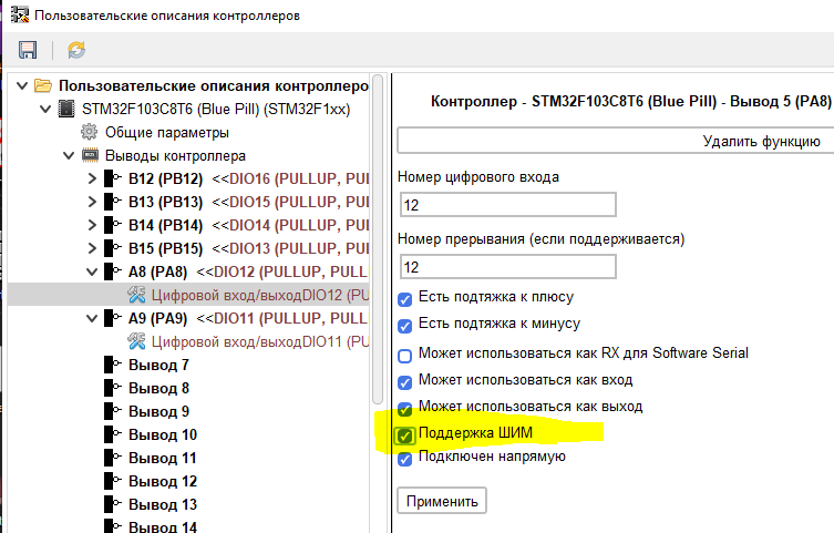
In accordance with these values, we set the parameters of the remaining pins. Some of the pins may be PWM outputs.
For these pins, do not forget to check the corresponding box.
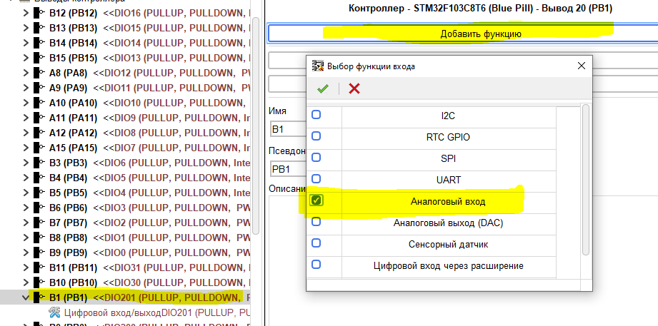
Some pins can be used as analog inputs.
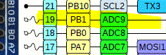
For them, we add one more function – “Analog input”.
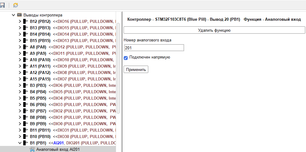
And in the properties of this function we set the necessary parameters obtained using the sketch.
After filling in the parameters of all pins, a situation is possible when the previously specified number is either not enough, or there are extra ones. This number can always be corrected on the “Controller outputs” branch.
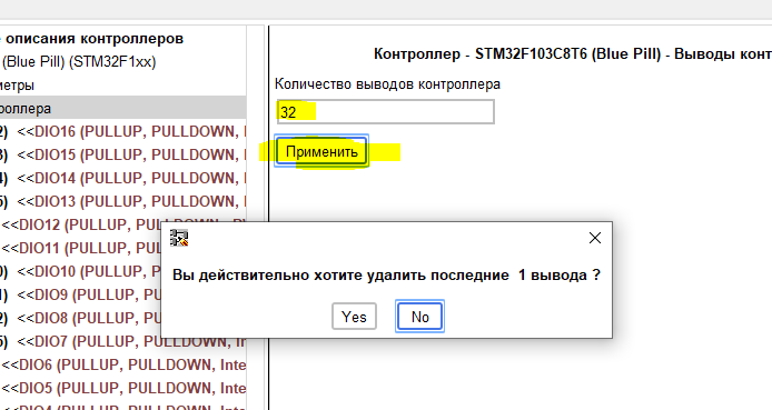
If the entered value is greater than the old one, then the required number of pins will be added to the end of the list, if it is less, then an additional request for deletion confirmation will be displayed first, and then the extra pins from the bottom of the list will be deleted.
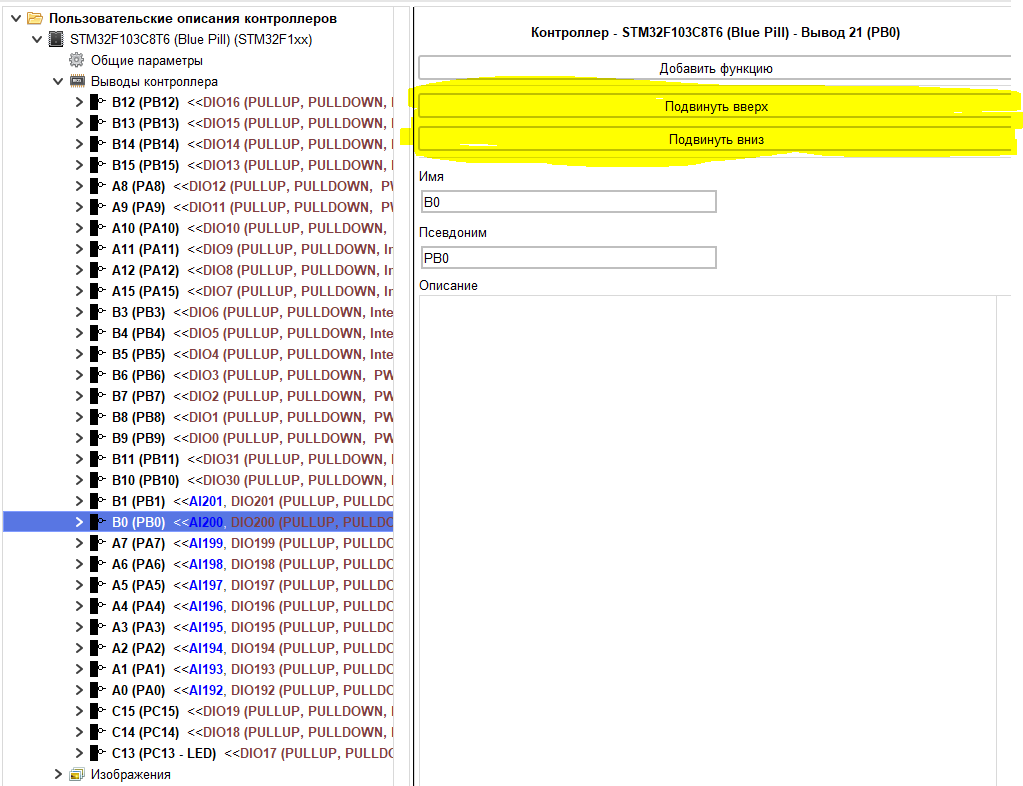
If desired, you can change the sequence of pins.
Then we add additional features. In accordance with the documentation, UART1 is displayed on pins RA9 and RA10.
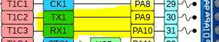
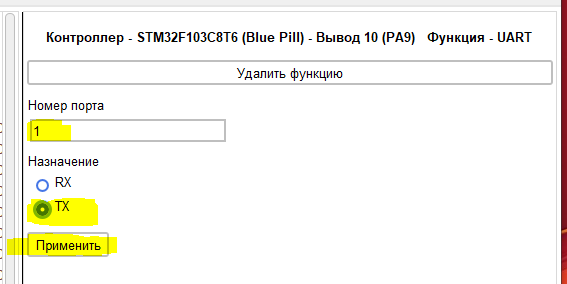
We add the UART function to the PA9 pin.
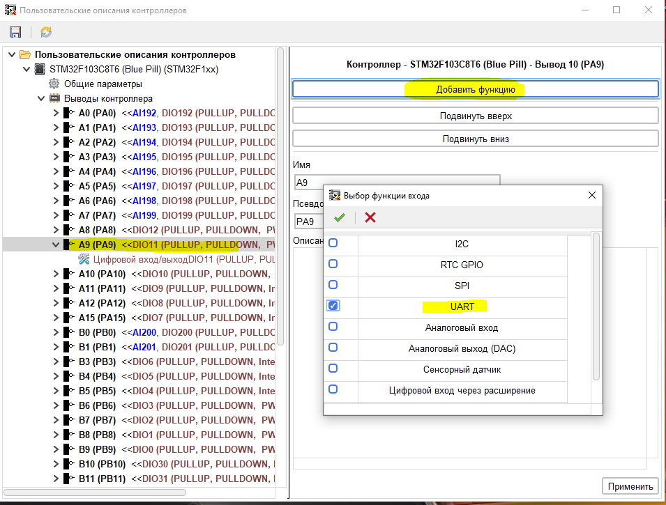
And fill in the parameters of this function.
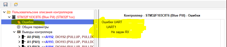
At any time, you can see if there are current errors in the description and what they are. If there are errors in the description, the “Errors” branch appears which contains their description.
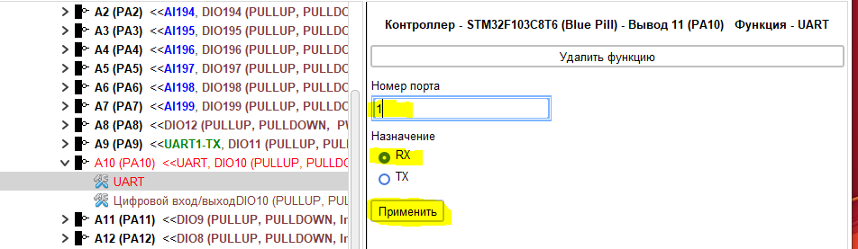
Add UART function for pin PA10.
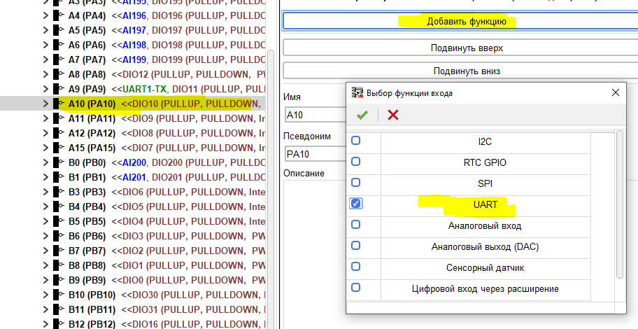
And fill in the parameters.
Errors in the description disappear.
Thus we describe UART2 and UART3.
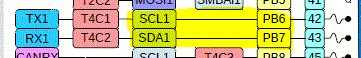
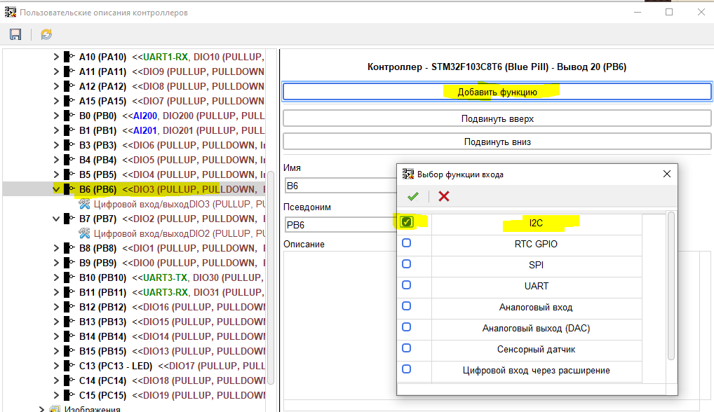
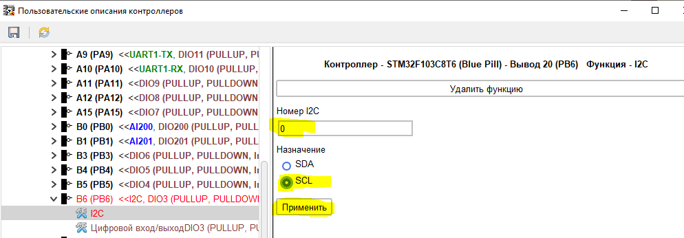
Let’s move on to the I2C bus. Currently, the FLProg program supports only one I2C bus. Therefore, we will describe only one. According to the documentation, the I2C bus is connected to pins PB6 and PB7.
Accordingly, we add the I2C function to the PB6 pin.
And set the necessary parameters (in FLProg, bus numbers start from 0).
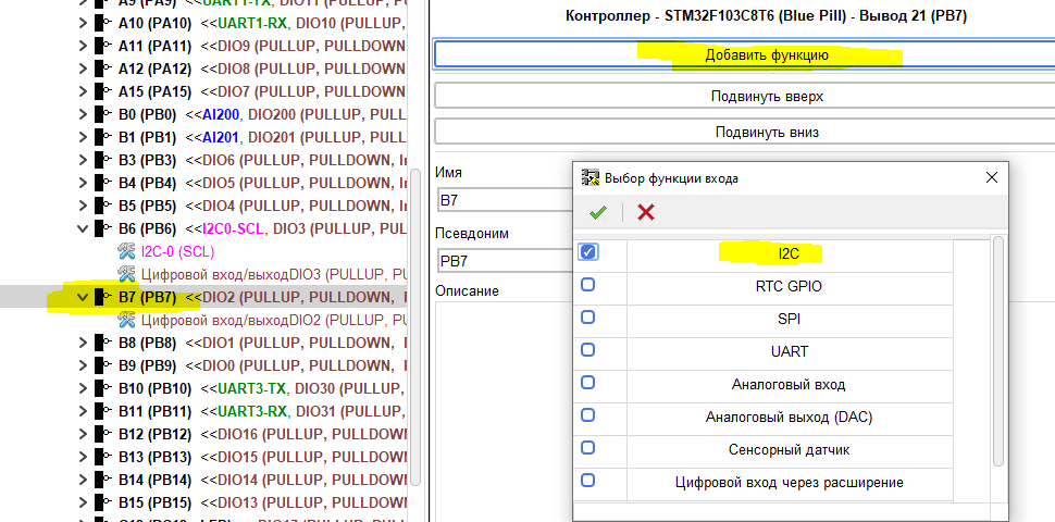
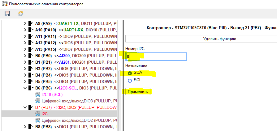
We do the same with pin PB7.
and parametrize.
Let’s move on to the SPI bus.
Add a function to the desired pin.
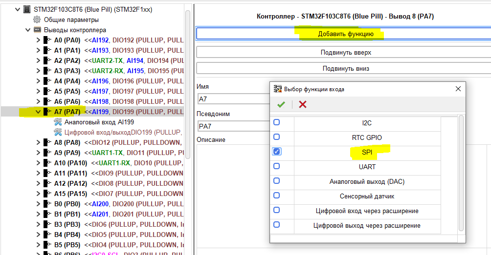
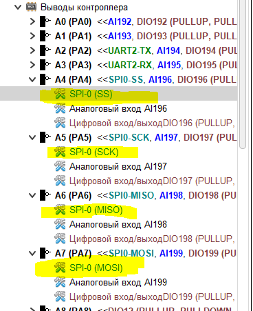
And we set up.
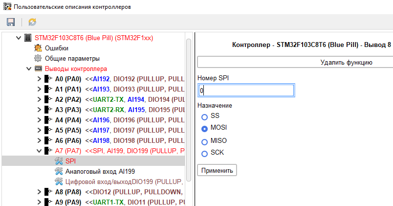
We complete the tire setup.
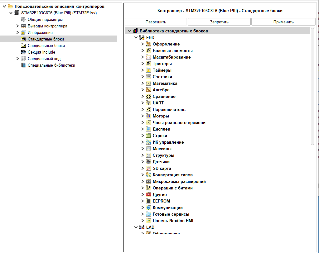
After setting up the pins, we proceed to setting up the composition of the standard library for this controller. By default, all standard library blocks are disabled for the new controller. I have so far decided that it is worthwhile to allow all building blocks for this controller for the time being.
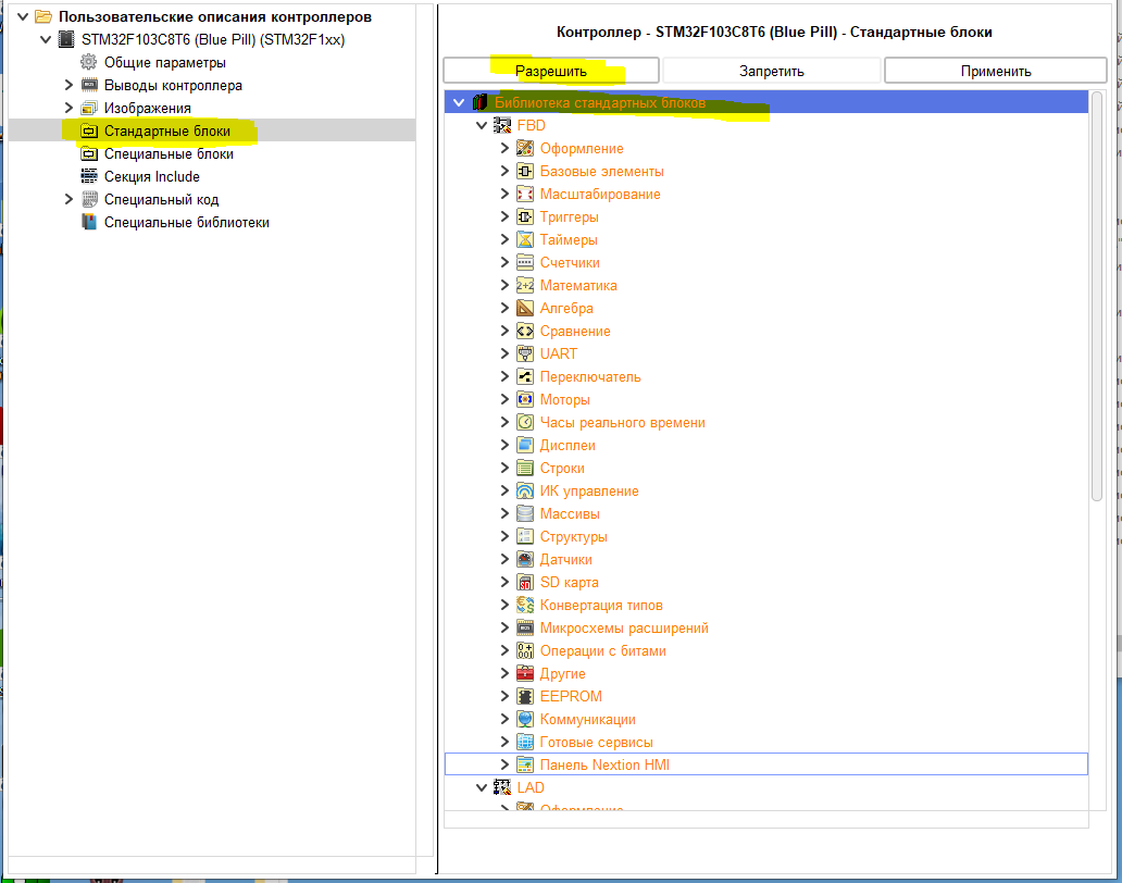
Accordingly, select the main branch of the library, click the “Allow” button and do not forget to click the “Apply” button for all changes. Allowed blocks are displayed in black.
Go to the pre-configuration branch of the Arduino IDE. This branch is used to set the parameters necessary for the Arduino IDE to start with the settings for the desired controller.
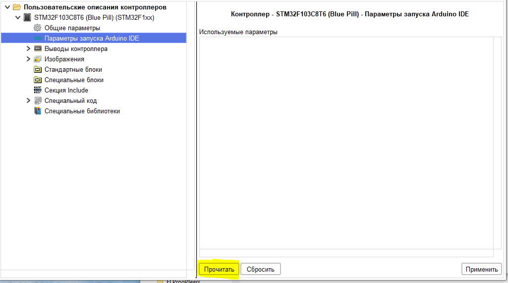
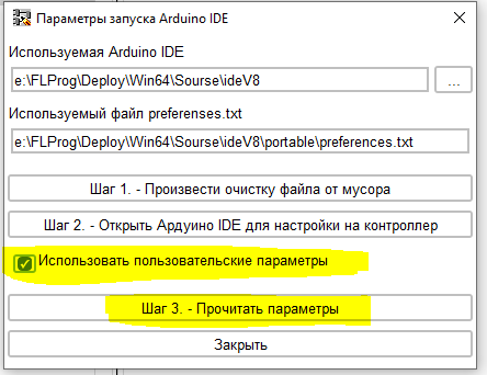
After clicking the “Read” button, a window for reading the necessary parameters will open.After clicking the “Read” button, a window for reading the necessary parameters will open.
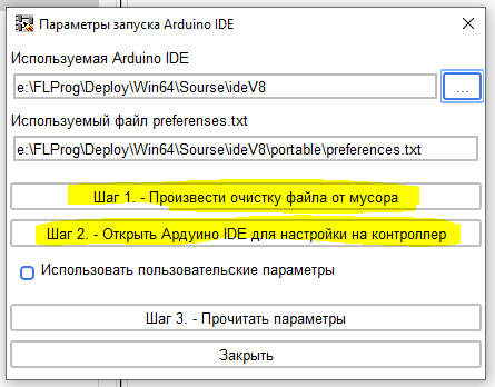
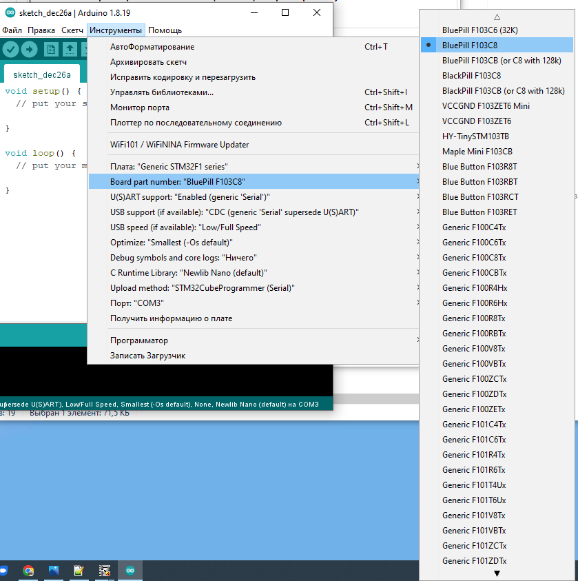
First, we clear the “preferences.txt” file from garbage, and then open the Arduino IDE. In it, select the required CPU.
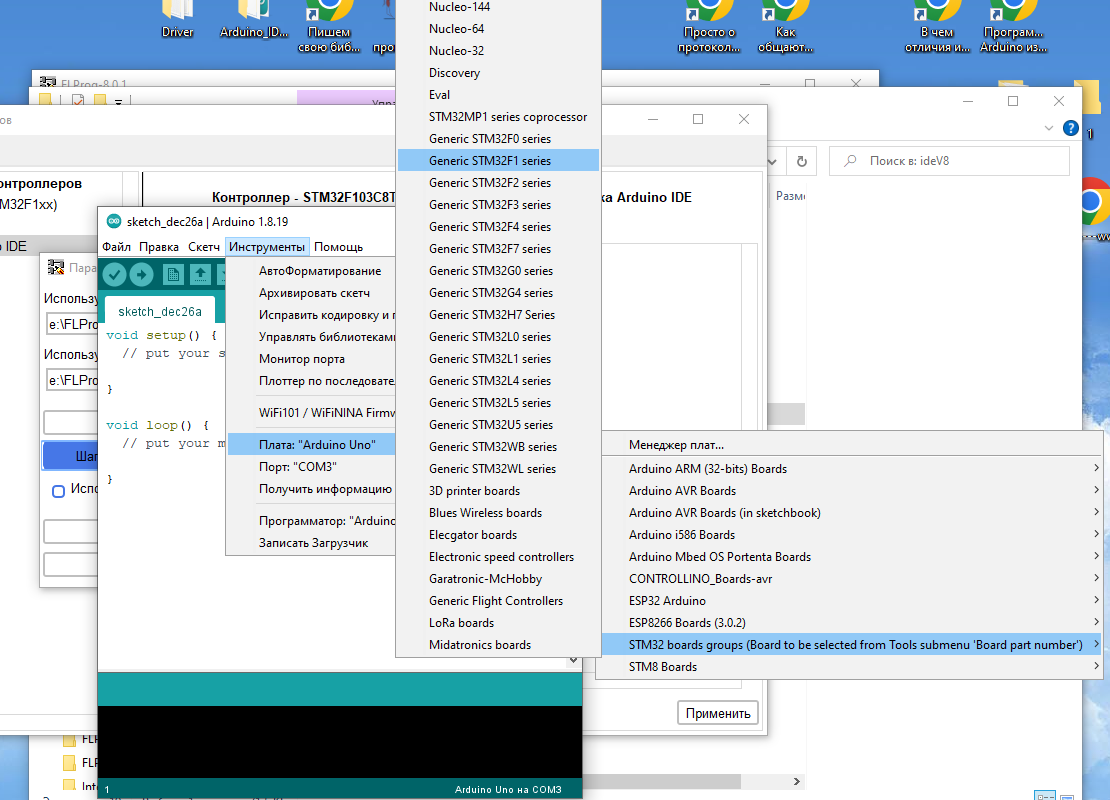
Then choose a specific board.
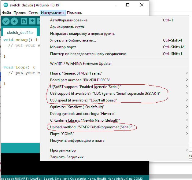
And adjust the rest of the settings.
After that, just close the Arduino IDE, and read the necessary parameters.
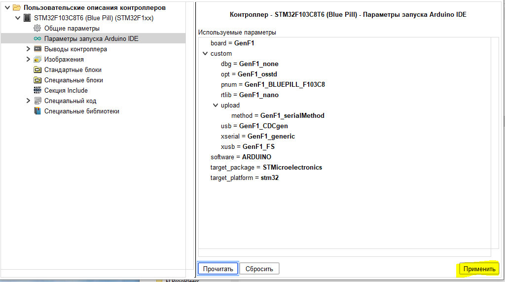
We check the received parameters.
Now let’s go back to the documentation and deal with UART0. According to the documentation, it connects to USB and does not have access to physical pins.
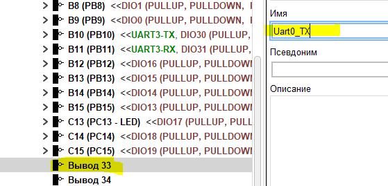
Let’s add two new outputs to the list of pins.
Let’s consider them virtual.
Set the name of the first virtual pin.
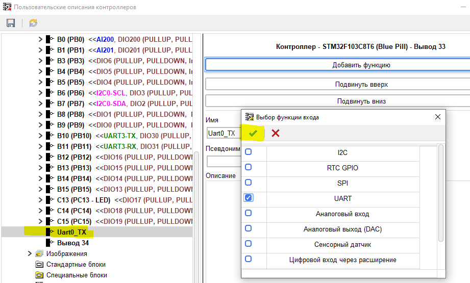
We add a UART function to it.
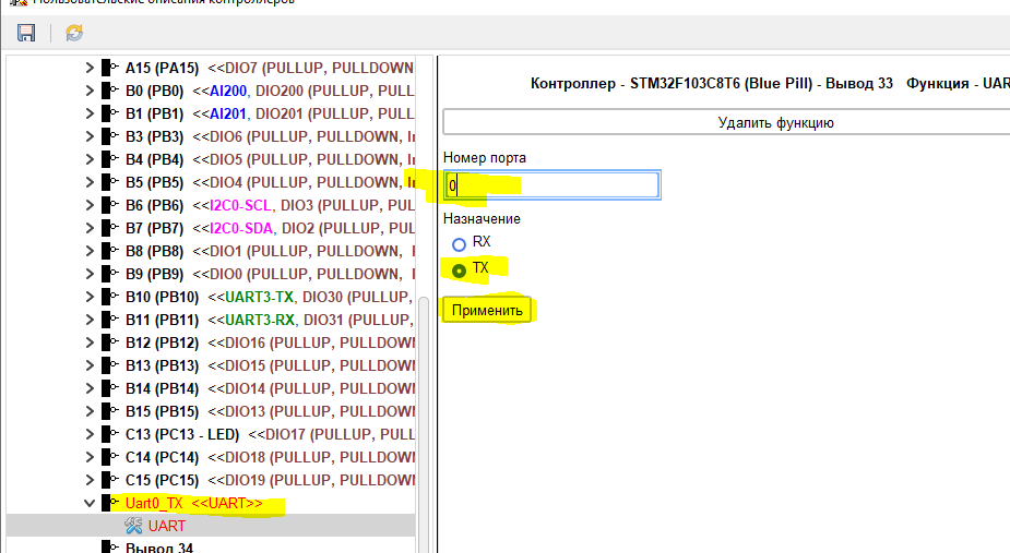
Fill in the parameters of the function.
Set up the second virtual pin in the same way.
Since these pins do not have any I/O functions, they will not appear for selection as such, but the UART will appear in the program.
On this, the creation of the controller description can be considered complete, and after saving it can be used in the program.


Здравствуйте! А как добавить(прописать) ядро stm32 в старые версии флпрог?
Будете ли, Вы, Сергей добавлять новые контроллера и tft дисплеи в программу, fbd очень мне понятен, работал в кодесис на сфс, но там только свои контроллера, хотелось бы на кортекс А8-А9 платы