Programmers, as a first lesson it is customary to use “Hello World”, the programmers of the microcontroller to the led blinked, but the electricians and electronics engineers to collect the control diagram of the contactor. Since the primary users of the program just they are, assemble the first lesson will be just this scheme.
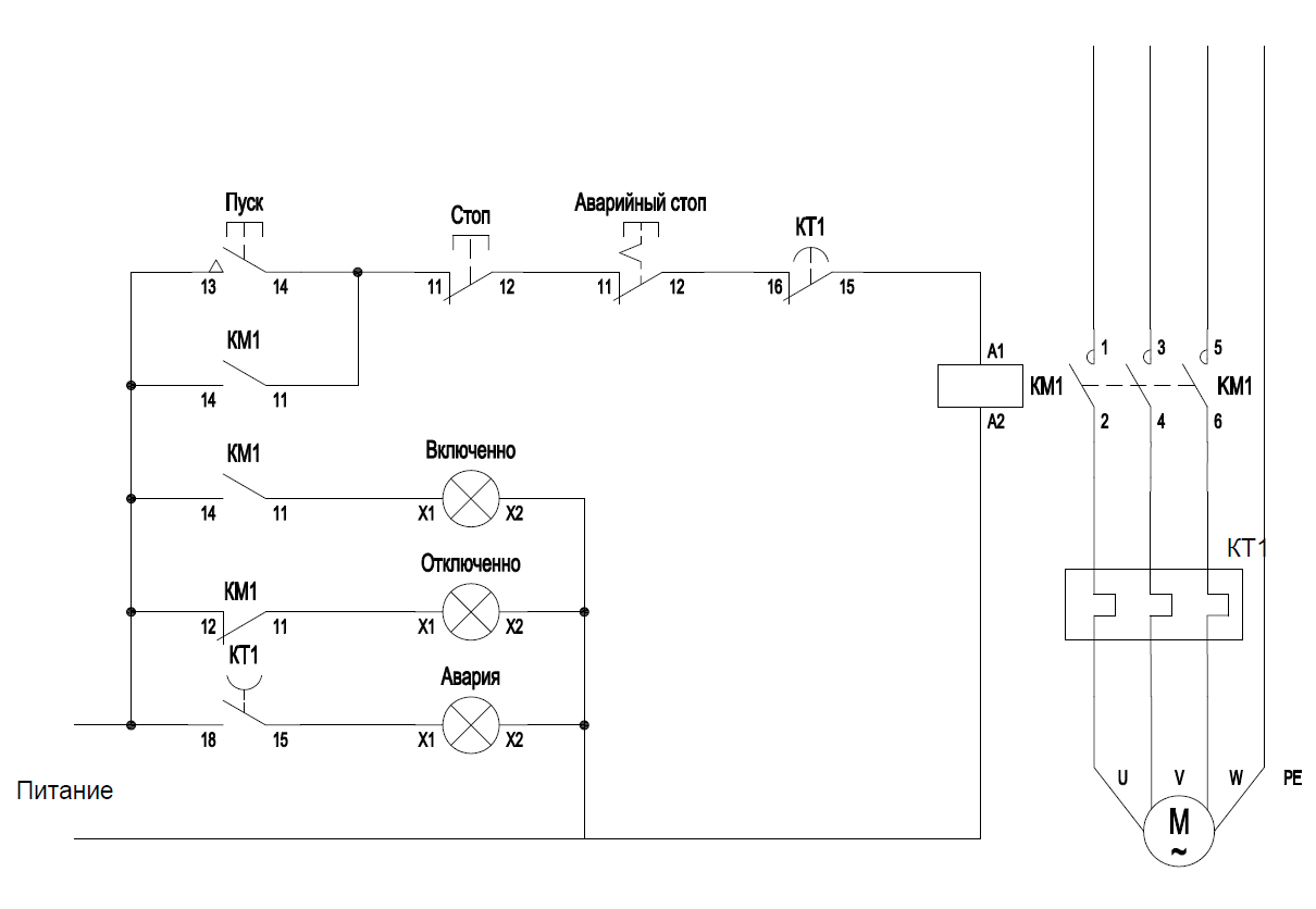
Standard circuit control contactor
Replace flowchart by the controller Arduino. Let’s leave aside the issues of noise immunity and shielding. This topic is for a separate and very large conversation. Our goal is to create a program FLProg appropriate logic. Therefore, distribute the test connection diagram.
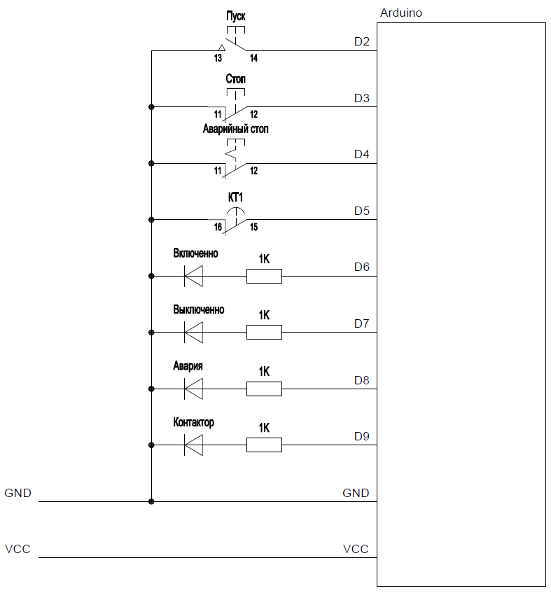
The role of the contactor in the test scheme performs led “Contactor”. Now try to program the controller.
FLProg run the program, click “Create new project”.

Opens the selection window of the controller and the programming language of the project.

To create a project, you can use either of the two programming languages (FBD and LAD) are standards in programming industrial controllers. In this tutorial we will create projects in both languages.
Please note that after you create the project in one of the languages to change it is impossible!
Clicking the controller opens the appropriate window, which will be presented supported by the Board.
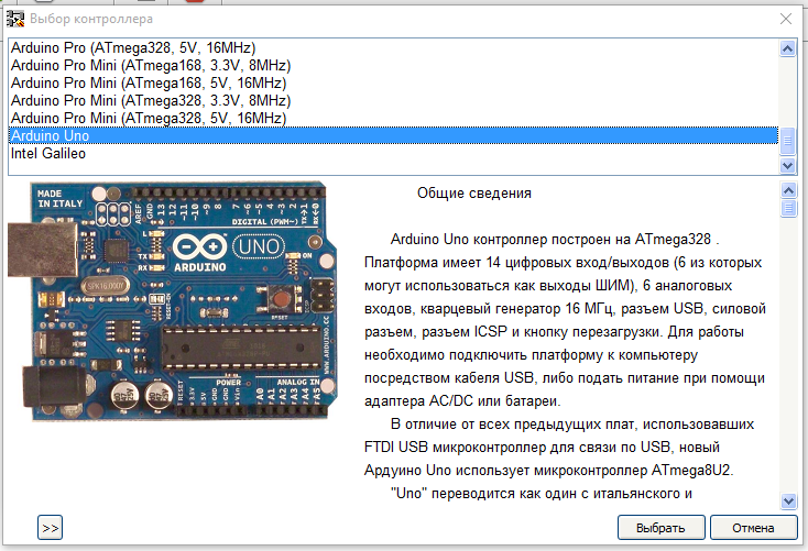
In this list select the desired controller.
Selected for a project controller to change at any time.
To begin, create a project in the language LAD.
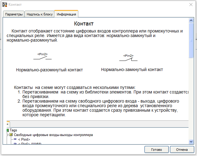
Ladder Diagram (LD, LAD, RKS) – ladder (ladder) logic. The syntax of the language easy to replace logic circuits, made on relay technology. The language is aimed at automation technicians, working in industrial enterprises. Provides a visual logic interface controller to facilitate not only the task of actually programming and commissioning, but and fast Troubleshooting the plug-in to the controller hardware.A program in ladder logic is visual and intuitive electrical engineers graphical interface, representing the logical operations like electrical circuit closed and open contacts. The flow or absence of current in this circuit corresponds to the result of the logical operation (true if the current flows; false — if the current does not flow). The basic elements of language are the contacts that can be figuratively likened to a pair of relay contacts or buttons. Pair of contacts is identified with a Boolean variable, and the condition of this pair — with variable value.Vary normally closed and normally open contact elements that can be mapped with normally closed and normally open buttons in electrical circuits.
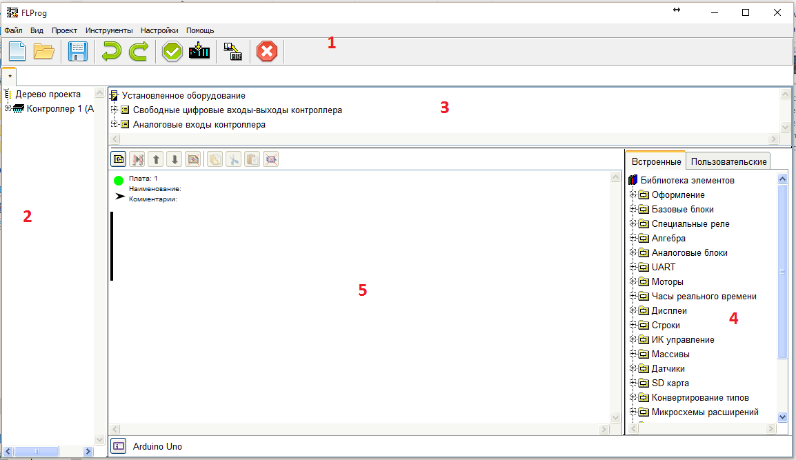
Working window of the program FLProg in FBD consists of several fields:
- The main menu
- The project tree (in this lesson it is not used, it will discuss in subsequent lessons)
- The tree of installed equipment. It presents equipment (intermediate relays, time relays, generators…), which is used in the project. In the new project, it contains only the inputs and outputs of the controller.
- A library of blocks. It is the equipment that may be used in the project. In this lesson we will only be interested in the folder “Base units”
- The scope of the scheme, which will actually draw the diagram. Scheme in FLProg is a set of circuit boards with the equipment.
To start, pull out the diagram pane contacts button. This can be done in two ways.
- Drag the appropriate entry from the folder “Free inputs and outputs of the controller” of the tree of the installed equipment on the diagram pane
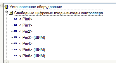
- To drag the block “Contact” from folder “Basic elements” library blocks.

As a result, the scheme appears to HUGO (semi – graphical notation) of the contact. In the case of dragging it from the tree of the installed equipment, the contact will be immediately linked to a digital input / output Board. If the contact block was pulled from a library of elements, it will abstract a contact without any binding.
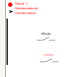
And in any case the contacts need to be parameterised. To do this, double-click on the contact. Opens the edit window of the block.
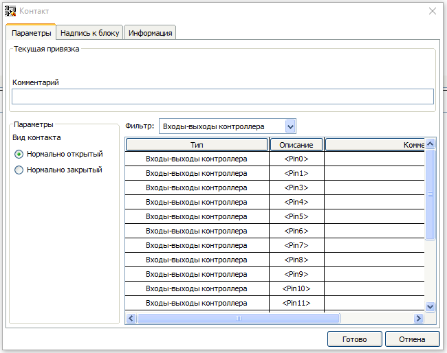
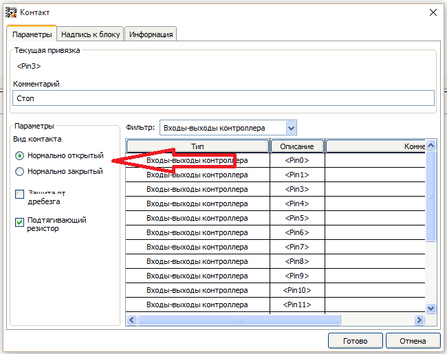
First and foremost, on the “Settings” tab you select a binding contact to the exit fee (if a contact is selected in the library blocks).
Then new options appear. Protection “bounce” and “pull up resistor”. Since in accordance with the scheme of the button is connected to GND, put a tick “pull up resistor”. “Protection from bounce” can not install, in this scheme it is not necessary.

On the tab “Label to block” write the name of the button that would show it on the diagram.

On the tab “Information” you can view information about this device.
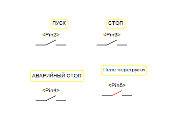
In the same way we take out the rest of the buttons and the contacts of the overload relay.
Then dragged from the block library device “Coil”. Also double click on it and opens the parameter adjustment of the coil.

Appointed by the coil of the intermediate relay K1, double-clicking on the corresponding item of the list.
Now we need to set the status of the contacts.
The program FLProg contact state corresponds to the level on the associated input card. If the input Board 0 – contacts are open if the 5V is shorted. Because the buttons in accordance with a scheme connected to GND and includes built-in pull-up resistors, when the closed button on the Board input will be 0, and when you let the button 5B. In accordance with these regulations put compliance contacts. This can be done in two ways.
- Double-clicking the contact and selecting the desired status in the editor block
- Right click on the contact in the popup menu, select the desired item.
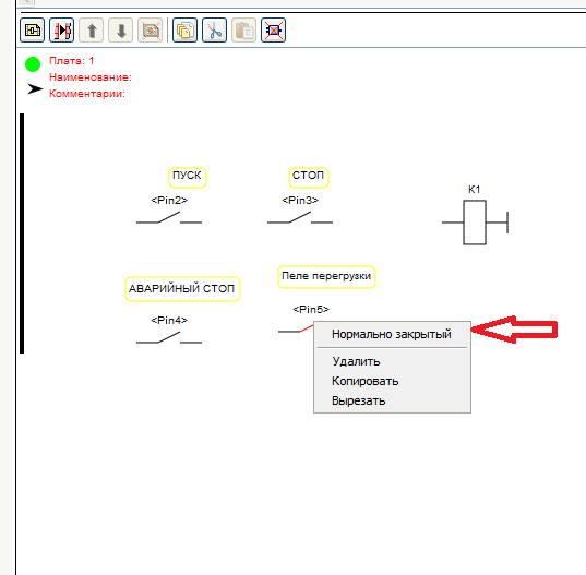
You should get here is the status of the contacts (the opposite to the standard scheme for the previously described reason)

Well, now you can start to draw a diagram in accordance with the standard schema of the starter. Connections are drawn by pointing the cursor on the first output element, pressing the left button, and without releasing the button, the connection stretches until the second of the connected output. If when approaching the cursor to them that followed, connection the output is colored in orange; it’s a connection you can connect

To create a block contact of the contactor, you can drag the contact K1 from the tree of the installed equipment at the scheme.

The result should turn out such a scheme. I think any electrician will understand her work (including invert state of contact inputs tied to the Arduino Board).

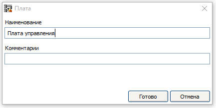
Thus, the first charge is finished. Let’s call it “control Board”. In order to assign a name to the PCB double-click on its header.
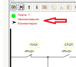
Opens a dialog to edit the header Board.
The green circle in the header indicates that the cost of correct and incorrect blocks on it. In the case of these units it will be red.
Now create another payment, click on “Add adapter”

It will control the outputs of the Arduino Board. To do this, drag on second charge four reels from the library of blocks and tie them to the outputs of the Arduino Board. Must get this picture
Coil with the associated pay outs relate to this: when you turn on coil in the project Board Arduino will be 5V when switching off 0
Then dragged from the tree of installed equipment necessary contacts (the two contacts of the intermediate relays, contact input overload relay), and then draw the required circuit is called an “output Control”.

The arrow in the header of the circuit Board enables to minimize the cost, which saves space on the desktop and speed up the program with large circuits. When you click on the arrow Board or folds or unfolds.

The download to controller for both languages are the same, so we consider it at the end of the lesson, and until you create a similar project in FBD.
FBD (Function Block Diagram) – a graphical programming language standard IEC 61131-3. The program is formed from the list of circuits to be performed sequentially from top to bottom. When programming uses sets of library units. Block (element) — is a subroutine, function, or function block (AND, OR, NOT, triggers, timers, counters, blocks of analog signal processing, mathematical operations, etc.). Each individual chain is an expression that is composed graphically from the individual elements. To the output of the unit is connected the next block, forming a chain.Within the circuit blocks are executed in the order of their connection. The result of the calculation circuit written in an internal variable or output it to the controller.
Create a new project in FBD.

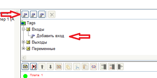
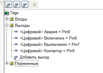
Fields 1, 2, 4, 5 in the program window are similar to those found in the language of the LAD. Field 3 here contains a tree of tags (inputs, outputs and variables). There are no pre-generated inputs, they must be created when needed. To create a new entry click “Add entry” or double-click on “Add input” in the tree tag.
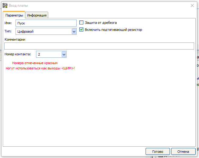
A window will open create a sign

Choose digital, new options appear. Write the name, choose the right Arduino Board input and put a tick “Enable pull-up resistor”.
In the same way add all the required inputs

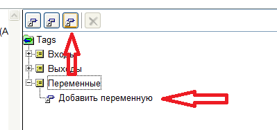
Then create a variable that is responsible for the condition of the contactor. To do this, either click on the button “Add variable” or double-click on the “Add variable” in the tree tag.
The configuration window of the variable
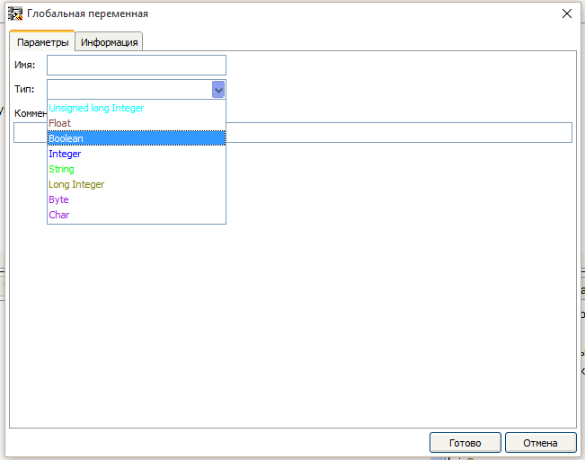
Select the variable type is Boolean and fill settings

Units of input in FBD correspond to the real pay outs, as follows. When the real input is 0 – the output block is False, when the Board input 5B the output of block True.
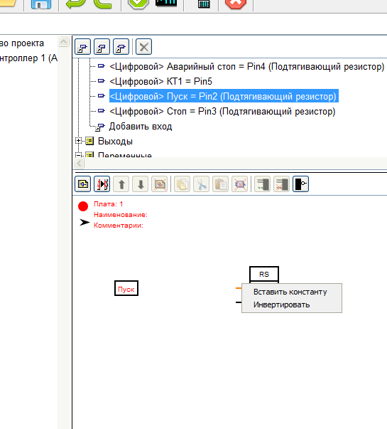
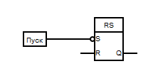
For memorizing the state of the contactor use the RS trigger. It is necessary to drag from the folder “Triggers” library units in the working area of the diagram.

RS-flip-flop, or SR-flip-flop — flip-flop, which retains its previous state with zero inputs and changes its output state when applying for one of its inputs units.
When submitting units to the input S (from the English. Set — Set) the output state becomes equal to the logical unit. But when the supply unit to the input of R (from the English. Reset — reset) the output state becomes equal to a logical zero.
When a logical zero at both inputs the output is kept the last state. When logical units on both inputs of in the case of the RS trigger output is set to logical zero, and in the case of SR trigger in the logical unit.
For that would turn on the contactor must submit to the S input, the input “start”. To do this, drag from the tree tag to the entry “START” in the workspace schema. If you remember that clicking start Board input a logical 0, it is clear that it is necessary to invert the signal from the button. To do this, move the cursor to the input S of the trigger and click the right mouse button. In the opened menu choose item “Invert”
Then connect the S input of the flip-flop output block input “start”. The establishment of the connection occurs, as well as in the language LAD.
Stop contactor takes place if:
Press “STOP” (log.1 block input “Stop” ) OR press “EMERGENCY STOP” (log.1 on the block of the input “Emergency stop” ) OR work out the thermal switch (log.1 block input “CP1” ). So we need the unit OR with three inputs.
Drag it from the library blocks folder “Base units”.
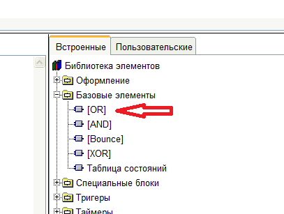
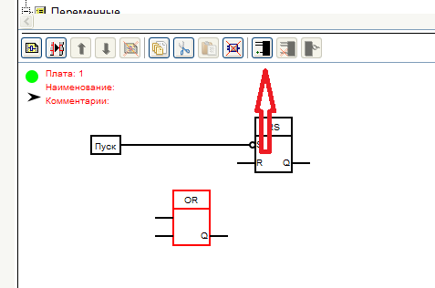
By default, a block OR two entrances. In order to add a third allocated block and click “Add entry”.
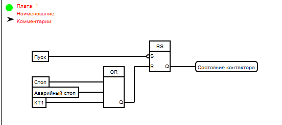
Transfer the inputs from the tree of tags and connect to the inputs of the OR block. And the output of the unit OR connected to the input R of the trigger.
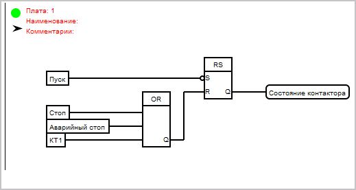
Then pick from the tree of the tag variable “State contactor” and a trigger output connected to the entrance of this variable. Must get this pattern:
This concludes the first charge and call her and LADе – “control Board”.
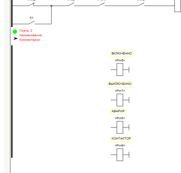
Then create a new card and immediately call it the “output Control”.
Next, create pay outs in accordance with the scheme. To do this, click on the button “Add output” length to double-click on the “Add output” in the tree tag. Outputs creating a digital type.

Drag on the second charge created outputs, input CP1 and the variable “State contactor” A

Спасибо Вам! Очень понятно и доходчиво расписано. Мне как новичку понятно. Здоровья и всех благ!!!
Здравствуйте!
Касаемо части на “FBD”.
Необходимо инвертировать все входы блока “OR”. Если не инвертировать, на выходе “RS” постоянный “0”.
Или я что-то упускаю?
Спасибо за Ваши труды!